Illumination Brush: Interactive Design of Image-based Lighting

Makoto Okabe, Yasuyuki Matsushita, Takeo Igarashi and Harry Shum

1. Motivation

1.1. Problem

Image-based lighting, or the environment map, is a method for representing a large-scale lighting environment surrounding the target scene as a texture map [Debevec 1998]. It compactly represents complicated incoming light from distant sources and enables real time rendering of the scene with realistic lighting effects [Sloan et al. 2002] (shown in Figure 1).

However, most systems rely on captured environments for image-based lighting [Debevec and Malik 1997; Havran et al. 2005]. Since a captured environment is not always available, a practical method for manually designing complicated lighting environments is in great demand.


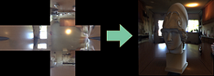
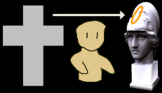
Figure 1: Image-based lighting is very useful, because it can represent complicated incoming light compactly as a cross image (left), and it can give us realistic rendering results (right).

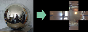
Figure 2: Environment maps are captured using a mirror ball and a high dynamic range photographs. However, environments that satisfy a designer's desire are not always available.

The artist might paint the environment map directly. Adobe Photoshop with HDRShop plugin is a popular for this task. However, this is labor intensive and it would be very difficult to obtain the desired rendering result, because of the non-linear mapping of a lighting condition and the appearance of objects. Figure 3 shows this problem in detail.


Figure 3: Labor intensive trials and errors: Even if the painter wants an orange highlight on the statuefs head (a), it is not clear which part he should paint. In (b), the painter tries painting an orange spot, but the orange highlight happens to appear at the cheek, and then in (c), the orange spot is painted again, but the orange highlight is not at the desired position yet. And also, since intensity of orange color is not clear, the painter has to experiences trials and errors for adjusting the color. As a result, painting environment manually makes the designer experience many trials and errors like shown in this figure.

1.2. System Overview

To solve these issues, we propose an appearance-based user interface for designing image-based lighting environments. Our system allows the artist to directly specify the appearance of the resulting image in a single screen by painting and dragging operations. Note that, using Photoshop, the painter has to modify the environment map and check the rendering result by turns, which means that the painter has to check two screens for one task. We overview the process of designing image-based lighting in. Figure 4.


Figure 5: Our system constructs an image-based lighting model that produces the desired (and painted) appearance by solving the inverse shading problem. (a) The user paints the desired color appearance. (b) The diffuse lighting environment is recovered. Also, the user paints highlights. (c) Now both diffuse and specular lighting environments are recovered. (d) For comparison, the final image rendered by ray-tracing using the designed image-based lighting environment (the vertical cross maps of diffuse and specular lighting on the top and bottom respectively) is shown.

2. Uniqueness and Approach

We propose an appearance-based user interface for designing image-based lighting environments. Our system allows the artist to directly specify the appearance of the resulting image by painting and dragging operations.

2.1. Diffuse Brush

The "Diffuse Brush" allows the user to design view independent diffuse lighting effects. As the user paints, the system immediately estimates the corresponding illumination and updates the screen. Figure 6 shows this process.

2.2. Specular Brush

The "Specular Brush" allows the user to design view-dependent specular lighting effects. The materialfs specular properties, such as shininess, are used to back-project the user input onto the environment map.


Figure 6: The recovered lighting environment is shown in the bottom-right sphere.

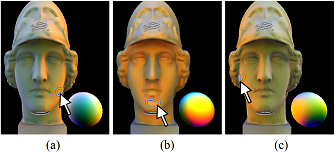
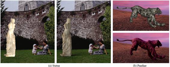
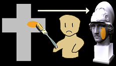
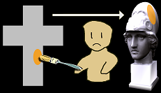
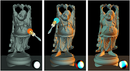
Figure 7: Orange highlights and white highlights are painted, and a rendered image from a different viewpoint is shown. The light source distribution estimated from the user input is visualized in the vertical cross.

2.3. Global Rotation

The user can rotate the entire environmental lighting by a simple dragging operation on the object surface.


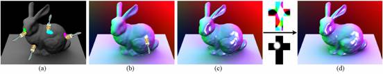
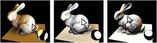
Figure 8: The user clicks and drags the white-lit part to rotate the lighting environment. The lighting environment rotates smoothly so that the surface colors under the mouse cursor stay constant.

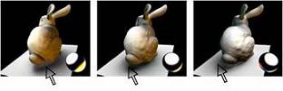
Figure 9: The user can also click and drag the shadow under the bunnyfs tail.

2.4. Stroke Manipulation

The result of a paint operation is stored as a stroke on the object surface, and the user can modify its color and position later.


Figure 10: The user paints a gray light effect on the armor, a black light effect under the chin, and an orange light effect on the left cheek (a). The user clicks and drags the orange stroke to the chin (b) and to the right cheek (c).

2.5. Algorithm

We briefly explain about the algorithm to estimate diffuse and specular lighting environments.

For diffuse lighting environment, the lighting environment is represented by spherical harmonics, by which the system renders a scene in real time. When the user paints a color on a 3D object using Diffuse Brush, the system automatically estimates spherical harmonic coefficients so that the resulting lighting environment lights the painted part as similar to the painted color as possible. As shown in Figure 11, the estimation algorithm of diffuse light source is in a least squares sense. To make the resulting light source have only positive values, we solve the constrained quadratic programming problem using Active Set Method.

For specular lighting environment, the lighting environment is represented as a cube map texture that can be rendered in real-time using a state-of-the-art graphics hardware. When a specular lighting effect is painted, the specular lighting environment is modified by simply back-projecting the painted color onto the environment map. A shininess parameter given by the user is used to determine the size of the light source according to the Phongfs shading model.


Figure 11: The left figure shows the algorithm to estimate a diffuse light source in a least square sense. The right figure shows the algorithm to project the painted lighting effect onto the cube map.

3. Results and Contributions

We show illumination design results and a useful application of adjusting photometric consistency when inserting synthetic 3D objects into photographs.

3.1. Illumination Design Results

Figure 12 shows qualitative results obtained by the authors using our illumination design system. Four lighting conditions in photographs are chosen as goal illumination environments. They are the scenes of early-morning, a hotel room, fine weather, and a night club. The user interaction time and the number of diffuse and specular strokes are shown below each result.


Figure 12: Illumination Design Results.

3.2. Adjusting photometric consistency of a synthetic 3D object in a photograph

When inserting a 3D object into a photograph, it is important to adjust photometric consistency of the 3D object. Our method is useful for this purpose. In this scenario, our system allows the user to load and display a background image behind the 3D object, and the user can paint and adjust the light effects of the 3D object so that it seamlessly matches the lighting conditions of the background photograph. Figure 14 shows the results of inserting a synthetic 3D object into a photograph by the authors. These results are rendered by a raytracer using exported image-based lighting environments designed using our system.

We also performed a user study to test the usability of our system in this scenario. Five computer science students, who are all novice users of the system and 3D graphics interfaces in general, participated the study. After presenting a brief tutorial, we gave two 3D models to each subject and asked him or her to insert each model to a photograph adjusting the illumination condition using the system. The subjects were allowed to work on the task until they are satisfied with the result and most of them spent approximately 30 minutes for the study including the tutorial. Figure 13 shows some of the resulting images. The subjects performed the task without major difficulty and reported that the function to pick a color from the background image was particularly useful for this task.


Figure 13: Illumination design results by the test users. The left images show the rendering results in default lighting conditions, and the right images show those in lighting conditions designed by the test users. The interaction time and the number of diffuse and specular strokes are shown below each result.


Figure 14: Adjusting photometric consistency of a synthetic 3D object in a photograph. The two images on the left are the result of inserting a 3D statue model into a photograph. The left image has an arbitrary illumination and the image on the right is rendered by a ray tracer using an image-based lighting environment designed by our system. The two images on the right are the result of inserting a 3D panther model to the photograph. The top and bottom images are before and after illumination design using our system.

References

DEBEVEC, P. E., AND MALIK, J. 1997. Recovering high dynamic range radiance maps from photographs. In SIGGRAPH, 369-378.

DEBEVEC, P. 1998. Rendering synthetic objects into real scenes: bridging traditional and image-based graphics with global illumination and high dynamic range photography. In SIGGRAPH 1998, 189-198.

HAVRAN, V., SMYK, M., KRAWCZYK, G., MYSZKOWSKI, K., AND SEIDEL, H.-P. 2005. Interactive system for dynamic scene lighting using captured video environment maps. In Eurographics Symposium on Rendering 2005, 31-42,311.

SLOAN, P.-P., KAUTZ, J., AND SNYDER, J. 2002. Precomputed radiance transfer for real-time rendering in dynamic, low-frequency lighting environments. In SIGGRAPH 2002, 527-536.